Deerfield and Roundabout Railway
LFLSRM Inc.
New Car Wheel Manufacturing
by J. G. Hook
(Scroll down for all illustrations. Captions above illustrations.)
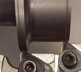
Second operation continued. As the carriage moves to the left the flange radius tool and the left carbide insert pass into area between the face plate and the back of the wheel provided by the fixture. The right carbide insert continues cutting the rough tread diameter.
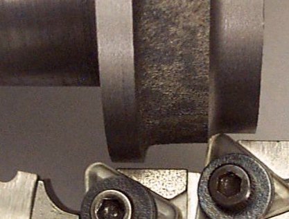
Second operation continued. When the right carbide insert nears the outside of the rough flange the power feed is disengaged. The carriage is then fed manually to simultaneously cut the the outside of the flange and continue cutting the rough tread diameter. Manual feed rate is approximately 0.004 ipr. The right carbide insert is set to produce an 80 degree flange angle.
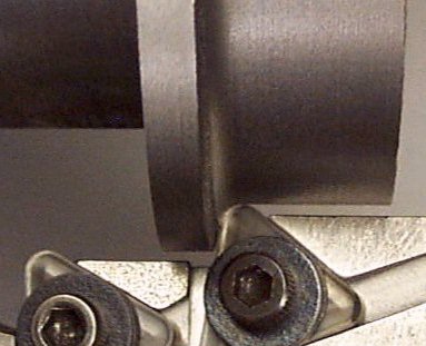
Second operation continued. After the carriage reaches the left side carriage stop, it is held there until the carbide insert no longer produces any chips. The carriage is then moved to the right to the previous starting position. Completion of the second operation produces the finished flange width. The compound slide dial reference "CP-A" controls the finished flange width and is adjusted in order to compensate for tool wear.
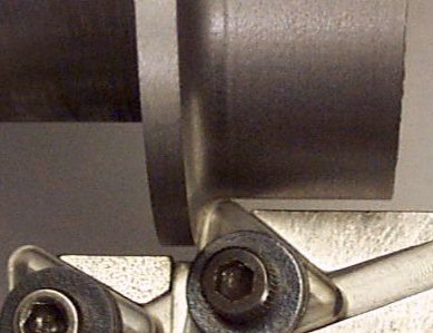
Third operation. Machining of second rough flange diameter of 4.900 inches and finished tread diameter of 4.500 inches. The compound slide dial is set to reference "CP-B," the cross slide dial is set to reference "CS-B" and the power carriage feed is engaged. Spindle speed 600 rpm., 786 sfpm., lathe power carriage feed rate 0.008 ipr. Setting the compound slide dial to reference "CP-B" moves the tool bits 0.005 inches to the right thereby preventing the right carbide insert from contacting the finished outside of the flange when the carriage reaches the left side stop. The cross slide dial reference "CS-B" controls the finished tread diameter and is adjusted in order to compensate for tool wear.